 Fraunhofer Institute for Transportation and Infrastructure Systems IVI
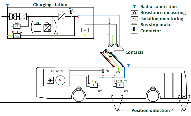
Implementing the technology in regular operation creates specific additional requirements for the system. The development aims in this case were to avoid making additional demands of the driver and to not cause any restrictions for the passengers.
Accordingly, the automated charging process must be able to identify all relevant system states and react to them appropriately in case of any discrepancies. An additional challenge was the distribution of the necessary interaction among several subsystems, which are generally provided by different collaborative partners. For this purpose, the respective automation tasks and interfaces had to be clearly identified. By doing so, the different subsystems can now be further developed, extended and recombined within other applications.
Under the monitoring of the TÜV Rheinland, a safety and operating concept was compiled based on the technical standard DIN EN 618511[1]. As a first step towards the overall concept, a risk analysis was conducted in compliance with the standard IEC 615082[2]. The implementation of the derived tasks and requirements was monitored and approved by the TÜV Rheinland.
The following framework conditions for the design of the automated charging process were derived from the knowledge gathered at the Fraunhofer IVI regarding the requirements for its use in regular bus operation. Subsequently, they were implemented by the automation solution.
- Each driver must be able to position a bus at the curb with an accuracy of 40 cm in the direction of travel and 30 cm laterally. The approach of the charging station is facilitated by »Kombibord« curbstones.
- The automated process must be easily integrated into the drivers’ regular work routine. The only information that the drivers will be provided with is status information about the charging process, but they will retain the option of canceling or terminating the charging process.
- The roadside contact hood has to be installed so that its lower edge remains at a height of at least 4.50 m above the road at all times.
- Energy transmission is to start within 0.5 sec of the contact closure.
- Energy transmission is to be initiated only if electric safety can be ensured.
- If a discrepancy or deviation is detected by one of the subsystems, the charging process is to be terminated automatically.
As demanded by the DIN EN 61851, the charging system is constructed as an electrically insulated system with a galvanic isolation from the grid input. This is realized by the installation of an insulating transformer within the charging station. During the recharging process, the electric safety for persons and facilities is ensured by connecting the electric earthing in the bus stop area with the vehicle’s chassis and additionally by monitoring the connection during the time of the energy transmission. Furthermore, an insulation monitor continuously checks the insulation resistance of the closed system circuit consisting of all components involved in the charging process. DC contactors inside the charging station and inside the vehicles serve to ensure the fast and secure electrical separation in fault case. These electrical switches are also used to realize the permanent separation of the contact system’s electrically active components, which can be touched by the maintenance staff while no charging process is going on.
[1] Electrical equipment of electric road vehicles - conductive charging systems for electric vehicles.
[2] Functional safety of safety-related electrical/ electronic/ programmable electronic systems.